 There was a comment on my Pseudo Sump post as follows:
s.k. nelson said...
i've wondered how this could be done, but how do you attach pipes to the outside of the structure and not the center. is it another style or what?
This has a few possible answers depending on s.k.'s acutal question. So I will address them all:
Possible Question #1: How do you visually get your profiles to "trim" the pipes to the structure boundaries?
There are a few ways you can show your structures. You can show the mesh of the model itself, the outline of the model itself or you can show a block of your choice.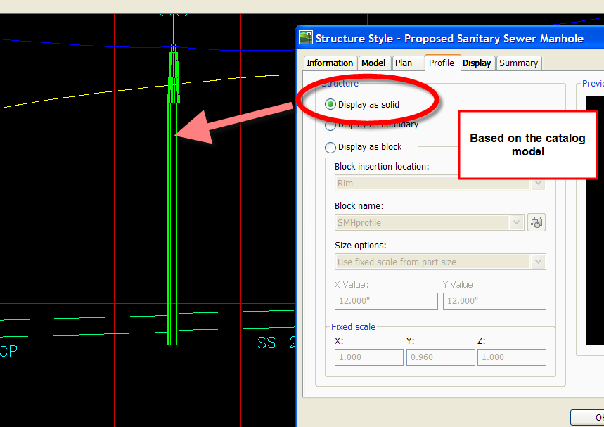


If you choose to show a block, the most popular option is to have the block size itself to match the model.
You can enable part masking to visually mask the joining of the pipes inside the manhole.

Possible Questions#2: How do you get your labeling to give you "Outside of Manhole to Outside of Manhole" pipe lengths instead of "Center of Manhole to Center of Manole" pipe lengths?
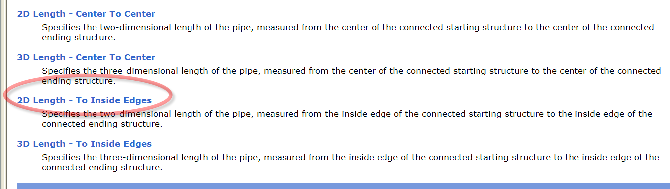
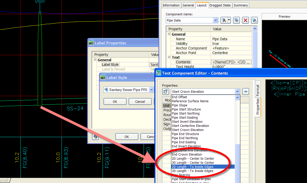
I believe this is new for 2007, because I remember looking for it in 2006 and not seeing it. In 2007, you can label structure to structure length, either 2D or 3D.
It is measured from the inside wall, so the thickness of the structure wall will make a difference. If those few inches are enough to bug you, go back into the parts builder and make some skinny walled structures.
If you need some help deciphering all of the choices in the text component editor- search help for: Part Properties Tab (Pipe Properties Dialog Box)

Possible Question #3: How do you actually get the model to only attach to the outside of the structure?
I don't think it will. I could be wrong. If you can get your labels to give you want you want as in my response to #2, and you can mask out the connection as in my response to #1, who cares? If you do care- maybe exploring the partsbuilder would be worth your time.
Nick from Engineered Efficiency is speaking at Autodesk University on the partsbuilder, so be there or be square!
Possible Question #4: None of the above?
you tell me :)


4 Comments:
Sorry, I had not responded sooner. My question was a little vague. After using your "psuedo sump" method/technique, my out going pipes appears below the sump of the manhole. I was curious how you handled it. From your pics it doesn't seem to be doing this.
I didn't know what to do to address it. I thought using a 1" or 2" floor sump or seeing if there was some setting to attach to the outside of structures versus the center. Using a thicker lineweight on the structure would probably hide it, but I thought I would ask.
Thanks for all your tips/tricks. They certainly help this newbie out.
check out today's post for an idea of what might be amiss.
Here in NZ, for subdivision design of sanitary sewers, we are required to show the drop ACROSS the manhole...not just at cl....so we need to be able to attach pipes at the structure inner walls and to publish the pipe levels at the inner wall points...C3D does not allow this type of design capability from what I can see and it also does not allow pipe network bands to publish pipe invert levels at the inner wall points in the pipe data band....bummer!...we would also like to be able to publish "DEPTH TO INVERT" for the ends of the pipes at the inner wall points. I wonder how many other folk would like this functionality rather than just designing on structure cl?
Peter.
Dana,
if i use masking to hide pipe within the manhole i also loosing the pipe (ellipse)attached to manhole in 90 degree. Is the way to resolve this? I found only way to hatch the manhole with solid non-plotting color... and bring to structure to top.
Is the another better way to show the pipe? Thanks.
Post a Comment