I also know that sometimes I do things the way that I figure out how to do them, and I am missing something obvious that other people do. If you have a different method, please let me know!
**These styles (pipe crossing, crossing labels, profile view invert labels) are not included in the standard Civil 3D templates. They must be created by your company (There may be some pretty close to this in the Civil 3D 2007 template, though)**
This is a three part process.
1) Add the pipe you would like to see in crossing to the profile using the PIPE tools
2) Label the pipe (as desired) using the PIPE tools
3) Label the invert of the pipe crossing using the PROFILE VIEW tools.
1) Add the pipe you would like to see in crossing to the profile using the PIPE tools
-Go to plan view and find the pipe you would like to show in crossing. Here is a storm pipe that crosses a sanitary line.
-Choose Draw Part in Profile View from the Pipes Menu
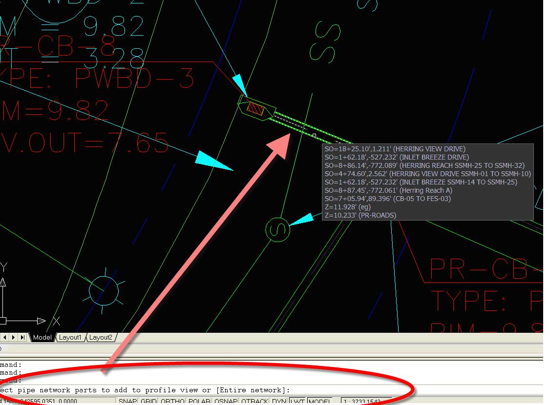
-Choose the pipe that crosses the sanitary pipe. (You can also choose multiple pipes that cross, but for now I will just choose one). Then, hit ENTER.
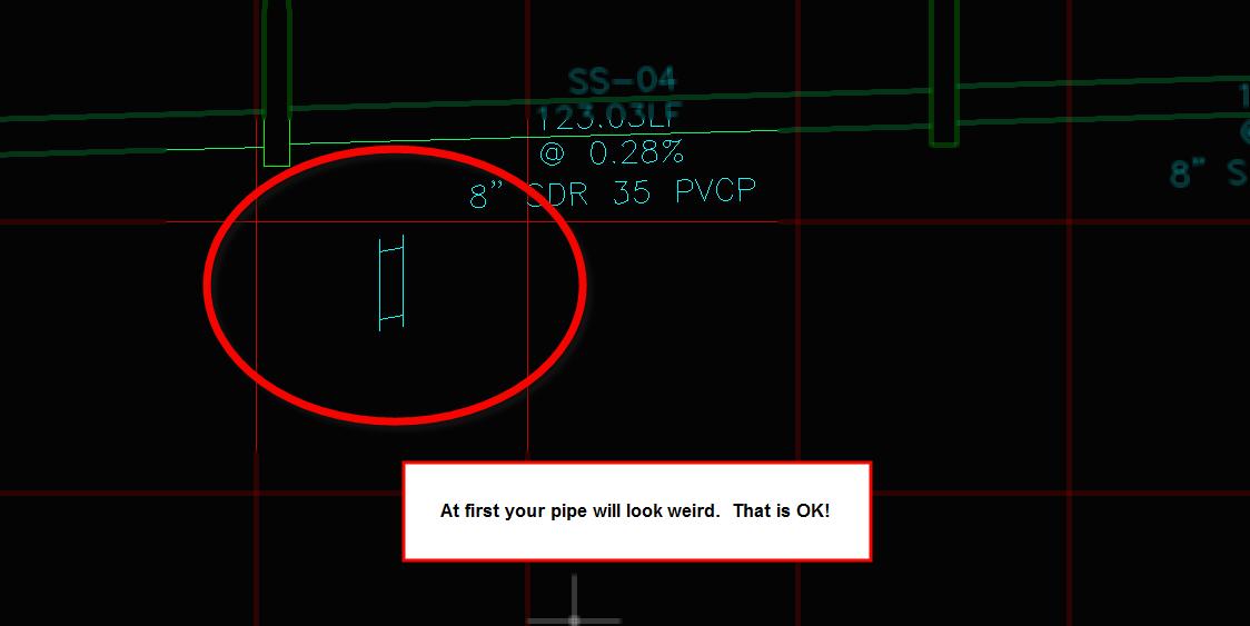
-Choose the PROFILE VIEW where that crossing belongs. At first it will look weird, that’s OK.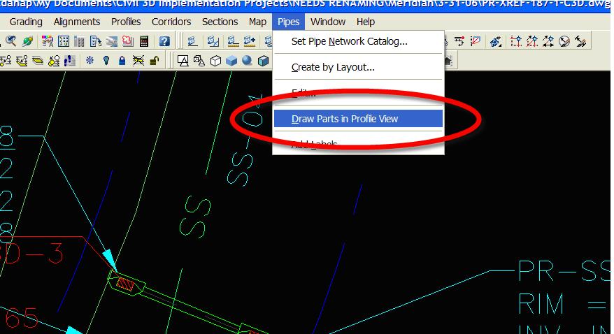
The way that pipes look in Plan, Profile and Cross Section are controlled by Pipe Style. We need to override the pipe style in this profile to look like a section or crossing.
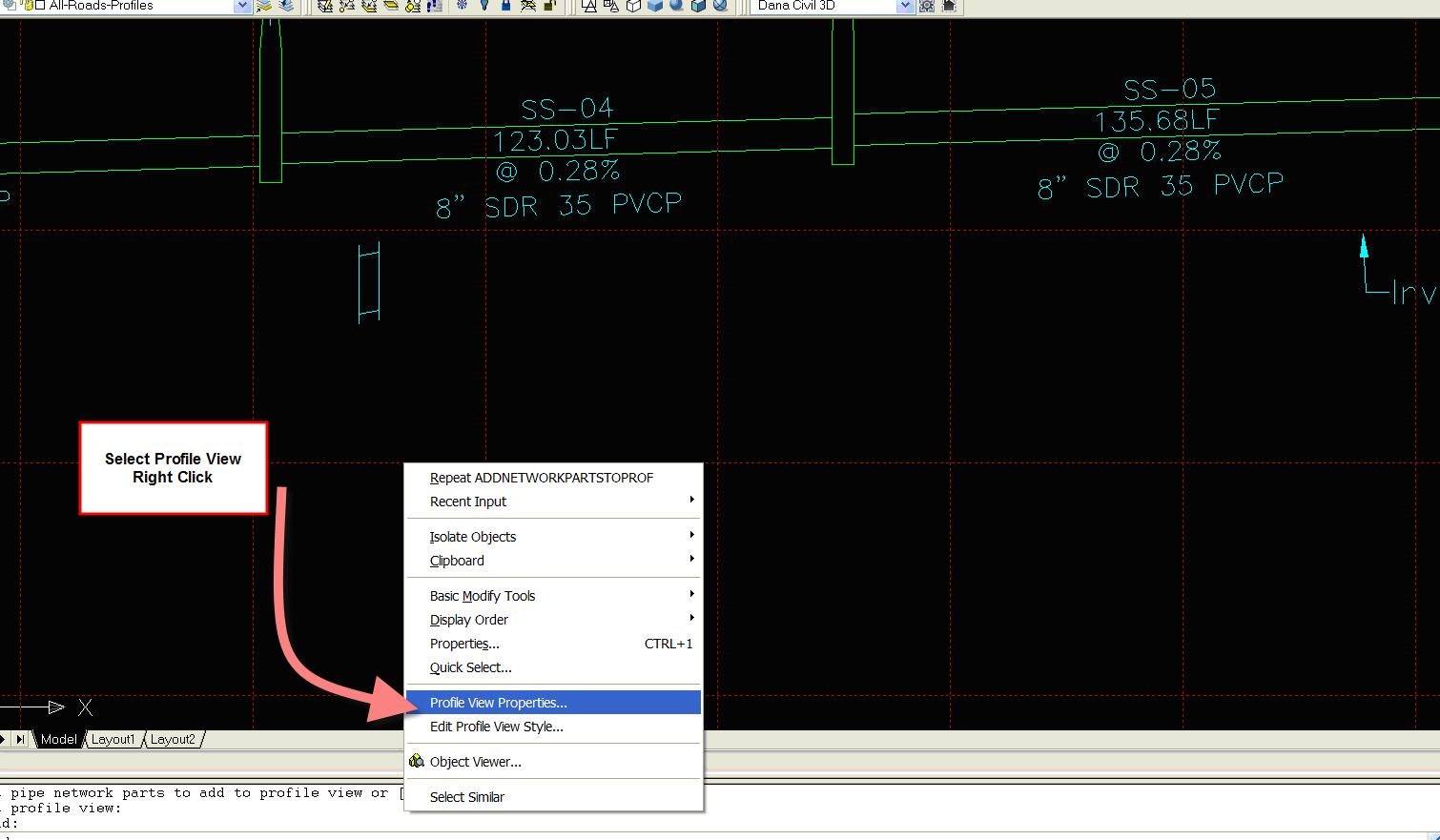
-Select the PROFILE VIEW and right click. Choose PROFILE VIEW PROPERTIES
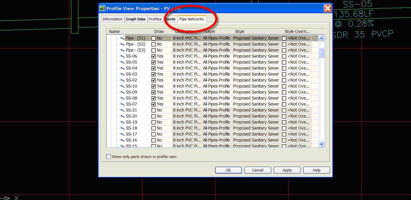
-Choose the PIPES tab
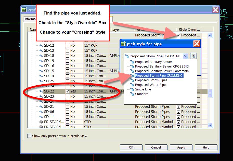
-Find the Name of the Pipe that you just added and check the “Style Overrides” Box.
-When you check that box, it pops up with the style choice box
-Choose one of the Crossing styles from your template and Click OK.
Now your pipe will look like a crossing. Remember- this is a profile view specific override. Changing the pipe style in plan or in another profile view will not affect this pipe in this profile view.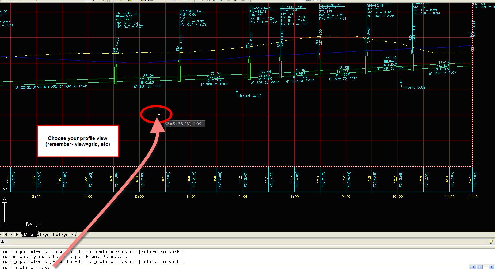
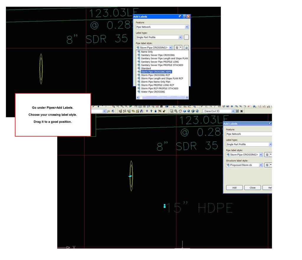
2) Label the pipe (as desired) using the PIPE tools
-Label the pipe elements of your choosing. Go under Pipes>Pipe Labels and Choose Single Part Profile and the Style of your choice. Click ADD.
-At first it will look weird. That is OK!
-Drag the label into a good position. The dragged state should be set up to orient the label properly. (Use the square grip to drag)
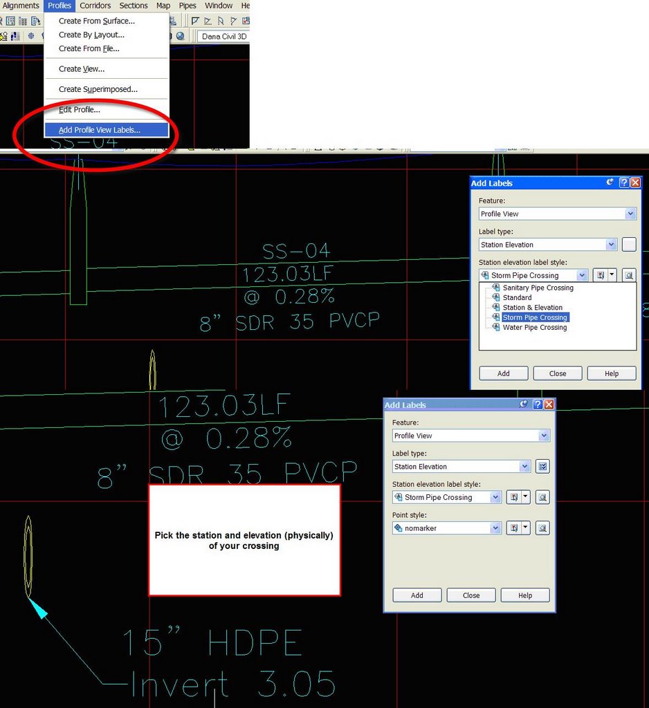
3) Label the invert of the pipe crossing using the PROFILE VIEW tools.
-Go under PROFILES>ADD PROFILE VIEW LABELS
-Choose STATION-ELEVATION and the styles of your choosing.
-Follow the command line directions and choose the Profile View
-Choose the “Station” of your pipe (you can snap to the endpoint of your pipe)
-Choose the “Elevation” of your pipe (you can snap to the endpoint of your pipe again)
-Drag the resulting label to stack up with your pipe material.


10 Comments:
Dana
Question with labeling a pipe crossing and I am using 2007, but have not checked this yet. When you change the style in 1 profile view to sanitary pipe crossing, doesn't the other profile view of the pipe change as well, i.e. if you want to show the pipe in the other view? Do you know if 2007 has solved this issue?
in 06 and 07 the override as shown in the post procedure applies ONLY to the profile view in question. the trick is not to change the PIPE STYLE but to OVERRIDE the pipe style in this view only.
Dana,
When I add the crossing pipe in the crossed pipe's profile, 3d 2007 displays not only the section of the pipe, but also the crossing pipe's profile as well as the structures. I overrode the crossing pipe style, but only the pipe profile disappeared, leaving the structures. Any Clues?
John Cobb
in 2007 the default is to add "entire network"
make sure you press "S" for selected parts only and ONLY add the pipe you want
Thanks, Dana.
Can you help me with extracting latitude & longitude information?
I've set my coordinate zone in Survey & set up a point group with a label style that should display lat & long, but the labels don't do that.
Thanks,
John Cobb
Dana,
I noticed how the drainage structures were labled in the drawing shown in this post. This is how our current company standards label structures, however I cant figure out how do make the label look like this. Could you please shed some light on this.
Thanks
Mike
mike, if you email me dana dot probert at civil3d dot com with a drawing that has the label style you've made so far, i will see where you are going wrong.
dana
I'm running problem with pipe crossing to show properly in profile view. My aligment loops around to itself and i have another road connecting the loop across and sanitary sewer run in center of road accordingly space with manholes.
When i try to draw part in profile view the crossing pipe is going accross to whole profile and make big mess. Anybody have and idea how to fix this..
Question. i have problem with civil 3d regarding paving profiles. i created 3 profiles like left curb , center and right curb but three are different profiles so i want to add 3 profiles together. how can i add in civil 3d 2008
That pipe crossing label technique is pretty sharp. Thanks.
Post a Comment