I am not a big believer in messing around with the pipes catalog.
For the most part, you can adapt the standard parts to act and look the way you want. For example, they might not have your EXACT manhole dimensions, but you can make a Structure Style and a Structure Label Style that handles the cosmetics and just grabs the Rim from the model.
Another example is Flared End Section. There is no flared end section catalog part (at least there wasn't in 2006. I honestly haven't looked in 2007 to be sure). But I just choose a simple box structure as the "model" part, and apply a FES block for plan and profile. The rims and inverts label just fine, and unless I wanted to rotate by pipe network in 3D and render it, I would never know the difference.
I also have a very strong feeling that in the near future there will be some sort of sharing library of parametric parts. Kinda like www.RevitCity.com . So I am not spending a lot of time making a perfect model part for everything when the standard parts can be "fooled" to do what I want.
With that being said...
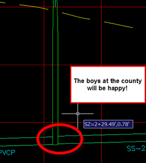
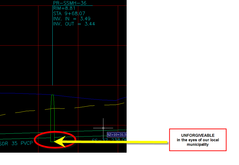
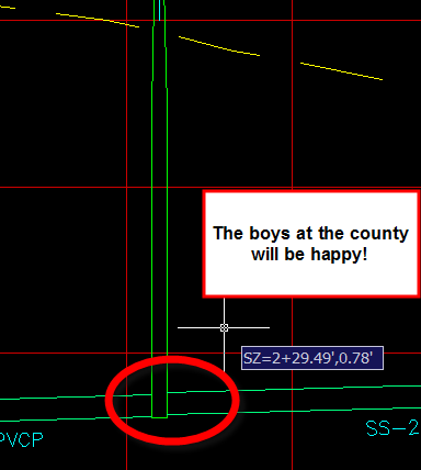
Our county will not accept profiles that even APPEAR to have sump.
By default, the structures in the catalog typically have a minimum of 6" of concrete under the invert. Which shows up on profiles like this (when you have a zero sump depth):
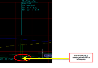
I played around with a few ways to try to get this little 6" chunk to go away, but there was no reliable way to get it to disappear without adding a size to the model. (if you have another way- let me know)
Like I said, I don't really like changing the pipes catalog- so here are my caveats:
CAUTIONS:
1) Changing the pipe catalog is not intuitive
2) By default, the pipe catalog is installed locally. If you change yours, your coworkers will not have your new part unless you either share it, or change everyone’s pipe catalog path to a network location
3) Overwriting a part will overwrite it. You always want to ADD sizes or parts, not overwrite them or erase them
4) Don’t do this until you are comfortable with structure styles and realize that you absolutely cannot make things look right without doing this.
5) Don’t do this often.
6) Don’t do this often
7) Don’t do this unless you have to
8) Only this particular procedure to parts that require this particular cosmetic improvement.
9) Reinstalling Civil 3D will erase your catalog customizations unless you save them in a backup folder before reinstall and move them back after the reinstall
10) Don’t do this for anything else EXCEPT this particular problem WITHOUT ASKING -IS THERE A WAY TO TRICK THE STYLE TO GIVE YOU WHAT YOU WANT FIRST??
THE PROCEDURE:
This works for both 2006 and 2007 with a minor difference. In 2007, the partsbuilder is right under the Pipes menu. In 2006, it was an undocumented tool. Type "PARTSBUILDER" in the command line to pull it up.
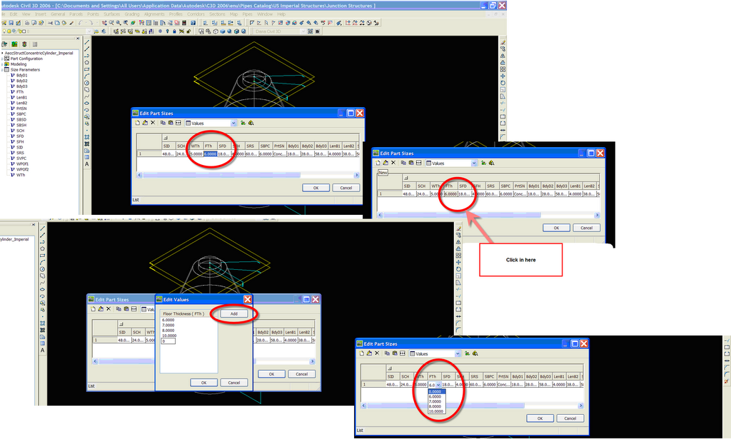
Choose the part that needs the help. In this case, I will add a NO FLOOR THICKNESS size to my concentric manholes. RIGHT CLICK on the part. Choose Modify Part Sizes
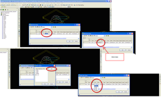
Expand SIZE PARAMETERS and right click on FTh (floor thickness) Make the FTh cell active Click the NEW button Click ADD, and add a 0 size floor thickness Click OK
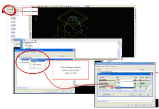
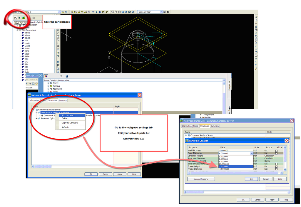
Confirm your new size is there and click OK Click SAVE PART FAMILY button, then the X to close the box.
Go to your parts catalog of choice and add that size to your list. Now it will look flush when you “size to network part” in the style. But keep in mind, the “model” now has no floor thickness, so it doesn’t really represent what a manhole looks like in real life.
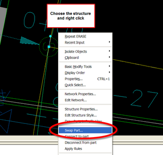
Also, if you already have the structures in the drawing, you will have to “swap parts”
For the most part, you can adapt the standard parts to act and look the way you want. For example, they might not have your EXACT manhole dimensions, but you can make a Structure Style and a Structure Label Style that handles the cosmetics and just grabs the Rim from the model.
Another example is Flared End Section. There is no flared end section catalog part (at least there wasn't in 2006. I honestly haven't looked in 2007 to be sure). But I just choose a simple box structure as the "model" part, and apply a FES block for plan and profile. The rims and inverts label just fine, and unless I wanted to rotate by pipe network in 3D and render it, I would never know the difference.
I also have a very strong feeling that in the near future there will be some sort of sharing library of parametric parts. Kinda like www.RevitCity.com . So I am not spending a lot of time making a perfect model part for everything when the standard parts can be "fooled" to do what I want.
With that being said...
Our county will not accept profiles that even APPEAR to have sump.
By default, the structures in the catalog typically have a minimum of 6" of concrete under the invert. Which shows up on profiles like this (when you have a zero sump depth):
I played around with a few ways to try to get this little 6" chunk to go away, but there was no reliable way to get it to disappear without adding a size to the model. (if you have another way- let me know)
Like I said, I don't really like changing the pipes catalog- so here are my caveats:
CAUTIONS:
1) Changing the pipe catalog is not intuitive
2) By default, the pipe catalog is installed locally. If you change yours, your coworkers will not have your new part unless you either share it, or change everyone’s pipe catalog path to a network location
3) Overwriting a part will overwrite it. You always want to ADD sizes or parts, not overwrite them or erase them
4) Don’t do this until you are comfortable with structure styles and realize that you absolutely cannot make things look right without doing this.
5) Don’t do this often.
6) Don’t do this often
7) Don’t do this unless you have to
8) Only this particular procedure to parts that require this particular cosmetic improvement.
9) Reinstalling Civil 3D will erase your catalog customizations unless you save them in a backup folder before reinstall and move them back after the reinstall
10) Don’t do this for anything else EXCEPT this particular problem WITHOUT ASKING -IS THERE A WAY TO TRICK THE STYLE TO GIVE YOU WHAT YOU WANT FIRST??
THE PROCEDURE:
This works for both 2006 and 2007 with a minor difference. In 2007, the partsbuilder is right under the Pipes menu. In 2006, it was an undocumented tool. Type "PARTSBUILDER" in the command line to pull it up.
Choose the part that needs the help. In this case, I will add a NO FLOOR THICKNESS size to my concentric manholes. RIGHT CLICK on the part. Choose Modify Part Sizes
Expand SIZE PARAMETERS and right click on FTh (floor thickness) Make the FTh cell active Click the NEW button Click ADD, and add a 0 size floor thickness Click OK
Confirm your new size is there and click OK Click SAVE PART FAMILY button, then the X to close the box.
Go to your parts catalog of choice and add that size to your list. Now it will look flush when you “size to network part” in the style. But keep in mind, the “model” now has no floor thickness, so it doesn’t really represent what a manhole looks like in real life.
Also, if you already have the structures in the drawing, you will have to “swap parts”


4 Comments:
great post! I've been wanting to post on my blog about this, but I've just been to darn lazy to do so. Thanks.
i've wondered how this could be done, but how do you attach pipes to the outside of the structure and not the center. is it another style or what?
FYI... the command "partsbuilder" is actually "partbuilder" in civil3d 2006.
I need some help. I have modified a stucture style to look like our normal profile structures and everything works great on my machine. When other people open drawings that I have created the stucture is about 1/10 the height it should be. The information is correct but it is graphically drawn wrong. Any ideas?
Post a Comment